
Originally published 2025-11-28 · Cyclone Bolt
The Criticality of the Connection: Why Every Heat Exchanger Bolt Counts
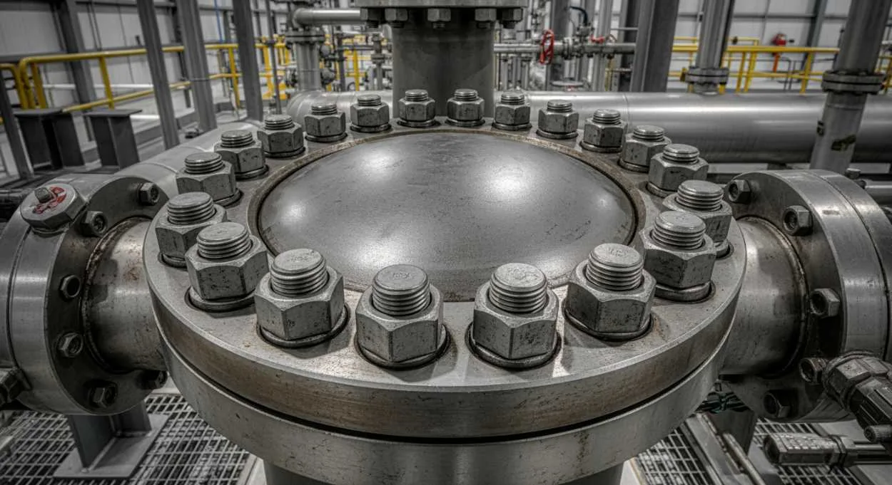
In the world of oil and gas, petrochemicals, and heavy industry, heat exchangers are the workhorses of the plant. They are essential for processes ranging from cooling and heating to condensation and separation. The tube bundle, where the heat transfer magic happens, is held together by critical bolted flange joints. These joints are not mere connectors; they are the pressure boundaries that keep corrosive, volatile, or high-temperature fluids contained.
Failure in a single bolt, or inconsistent loading across a flange, can lead to:
-
Catastrophic Leaks: Resulting in costly downtime, safety hazards, and environmental contamination.
-
Emissions Issues: Contributing to fugitive emissions that violate environmental regulations.
-
Equipment Damage: Uneven stress can distort the flange or damage the sensitive gasket, leading to premature joint failure.
Ensuring a leak-free, reliable joint requires moving beyond guesswork and relying on a single, standardized, step-by-step procedure. That procedure is built around the principles established by the American Society of Mechanical Engineers (ASME), specifically the ASME PCC-1 Guidelines for Pressure Boundary Bolted Flange Joint Assembly.
At Cyclone Bolt in Houston, Texas, we understand that even the most advanced, API 20E/20F certified fasteners are only as good as the assembly process. This comprehensive guide breaks down the proper procedure, focusing on the essential star pattern and multi-pass tightening method, ensuring the long-term integrity of your heat exchanger bundles.
Section I: The Science of Sealing – Achieving Proper Preload
A bolted flange joint, like those found on channel heads, shell covers, and tubesheets, is fundamentally a dynamic mechanical system. The goal of torquing is not just to make the bolts “tight.” The actual objective is to induce a specific, measurable bolt preload (tension) that creates enough compressive force (gasket stress) to deform the gasket and seal the flange faces against the internal pressure of the operating system.
The Role of Bolt Preload
When you torque a bolt, you are stretching it like a spring. This controlled stretching generates a clamping force. For a heat exchanger to operate safely, this clamping force must be sufficient to withstand three main forces simultaneously:
-
Internal Hydrostatic End Force: The pressure of the fluid inside the vessel pushing the two flanges apart.
-
Gasket Seating Force: The force required to compress the gasket material into the microscopic imperfections of the flange faces, creating a seal.
-
External Loads: Any additional forces from piping, thermal expansion, or wind.
If the preload is too low, the gasket will not seal properly, leading to an immediate leak upon startup. If the preload is too high, you risk yielding the bolt material or crushing the gasket and permanently deforming the flange. Precision is paramount.
The Problem of Friction (The K-Factor)
Torque applied to the nut is largely lost to friction. In a standard bolted joint, only about 10% to 20% of the applied torque actually translates into useful bolt tension (preload). The rest is consumed by friction:
-
Friction between the nut threads and the bolt threads.
-
Friction between the nut face and the washer/flange surface.
This relationship is governed by the K-factor, or “nut factor.” Because friction is so variable, using the wrong lubricant or insufficient lubrication can drastically change the actual preload achieved, even if the torque wrench reads the correct value. This highlights the critical nature of the preparatory steps detailed below.
Section II: Pre-Assembly: The Seven Essential Steps (ASME PCC-1 Foundation)
Before the wrench touches a nut, the integrity of the entire joint is determined by preparation. ASME PCC-1 emphasizes that proper assembly begins with material verification and cleanliness.
1. Fastener and Flange Inspection
Every component must be checked for fitness.
-
Fasteners: Inspect bolts, studs, nuts, and washers. Check for thread damage, burrs, corrosion, or pitting. Bolts must be the correct grade (e.g., ASTM A193 B7) and length, ensuring at least two threads are visible past the nut after tightening.
-
Gaskets: Ensure the correct gasket type, size, and material compatibility with the process fluid. Never reuse an old gasket.
-
Flange Faces: The sealing surfaces must be clean and free of rust, paint, grease, or tool marks that could compromise the seal.
2. Alignment Verification
The flanges must be parallel and centered. Flange misalignment is a primary cause of joint leakage.
-
Non-Parallelism: Flange faces must be parallel. If the gap between flanges is not uniform, the joint will tighten unevenly, creating localized stress concentrations that crush the gasket on one side.
-
Lateral Shift: The bolt holes must be properly aligned to allow free insertion of the fasteners.
3. Material and Quality Assurance
The foundation of a reliable flange joint is high-quality, traceable hardware.
-
Certified Materials: Verify that your bolts meet demanding standards like API 20E (Alloy and Carbon Steel Bolting) and API 20F (Corrosion-Resistant Bolting). These specifications are critical in high-pressure, high-temperature, or sour gas environments, ensuring material strength and traceability.
-
Coatings: Check the bolt coatings. Coatings like PTFE or specialized plating must be compatible with your target torque values, as they directly influence the K-factor.
4. Lubrication: The Preload Controller
Lubrication is arguably the most important preparatory step for controlled torquing. It minimizes friction, reduces the risk of galling (cold welding), and ensures that the applied torque translates predictably into tension.
-
Apply Anti-Seize: A specific, high-quality anti-seize compound (often molybdenum disulfide or nickel-based) must be applied to the load-bearing surfaces: all engaging bolt threads and the face of the nuts (the surface that contacts the washer or flange).
-
Consistency is Key: Apply the lubricant evenly. The type of lubricant used directly dictates the target torque value. A change in lubricant requires a re-calculation of the torque target. For guidance on selecting the correct industrial lubricant based on temperature and service, refer to expert resources like those published by industrial maintenance leaders: The Basics of Industrial Lubricant Selection.
5. Gasket and Bolt Installation
Position the new gasket carefully. Insert all bolts and nuts, ensuring they are hand-tightened. This provides the initial low-level, uniform compression needed before power tools are engaged.
6. Determine Target Torque
The final torque value must be calculated based on the bolt material strength (yield strength), the desired gasket stress, the thread dimensions, and the K-factor (lubricant). Never use generic, unverified torque tables; always follow the values specified in your company’s procedure or the OEM documentation.
7. Numbering the Bolts
Before starting the tightening procedure, all bolts must be numbered. This is crucial for following the cross-pattern (star) sequence accurately. Start with Bolt #1 and proceed sequentially.
Section III: The Multi-Pass, Star Pattern Torquing Procedure
The key to achieving a successful seal on large, multi-bolt flanges (like those on heat exchanger tubesheets) is the controlled application of load across the flange face. This requires two techniques: the star pattern (or cross-pattern) and the multi-pass tightening sequence. The industry standard, ASME PCC-1, dictates this phased approach to ensure uniform gasket compression.
The Star Pattern (Cross-Pattern)
The star pattern minimizes bolt-to-bolt interaction and prevents warping of the flange by distributing the load equally from the center outward.
How to Execute the Star Pattern:
-
-
Start at Bolt #1.
-
Choose the bolt diagonally opposite to it, which will be the next bolt in the sequence (e.g., Bolt #5 in a 12-bolt flange).
-
Continue moving across the diameter of the flange, ensuring the tightened bolts are evenly spaced around the circle.
-
The pattern should look like a star that evenly covers the flange perimeter.
-
The Multi-Pass Tightening Sequence
The multi-pass method ensures that the gasket is compressed incrementally and uniformly, allowing the gasket material time to creep and relax into its final position without being crushed. This process typically requires five distinct tightening passes.
The sequence begins with the First Pass, tightening all bolts using the Star Pattern to a torque value of 20% to 30%of the final target torque. The rationale here is to achieve initial, uniform contact and fully seat the gasket. Next is the Second Pass, where you again use the Star Pattern but increase the torque to 50% to 70% of the final target. This step significantly increases the clamping force, further compressing the gasket and minimizing bolt load scatter.
The Third Pass is the critical step: tighten all bolts to 100% of the final target torque, still utilizing the Star Pattern. This reaches the minimum required design preload and fully seats the joint for operation.
Following the star pattern passes, the procedure transitions to verification and load equalization using circular patterns. The Fourth Pass involves tightening all bolts to the full 100% target torque, but this time moving in a Circular Pattern (starting at Bolt #1 and moving sequentially to #2, #3, etc.). This is a “chase” or “ringer” pass designed to equalize the load and compensate for elastic interaction (the reduction in load on neighboring bolts caused by tightening a new bolt). An optional Fifth Pass involves repeating the Circular Pattern at 100% target torque until no further nut rotation is observed. This confirms full consolidation of the joint and ensures the load is stable.
Important Note on Flange Warping: The star pattern is essential because tightening one bolt creates a corresponding elastic deformation (or ‘lift’) on the bolts nearest to it. By jumping across the diameter, you distribute this lift symmetrically, keeping the flange faces parallel and avoiding permanent bending damage.
For a deeper technical dive into the bolting sequences and the role of standards in safety, consult the experts at the American National Standards Institute (ANSI) and their discussion on industry guidelines: ASME PCC-1-2022: Pressure Boundary Flange Joints.
Section IV: Advanced Techniques and Post-Assembly Integrity
While controlled torquing is the most common method, large or critical heat exchanger flanges often employ advanced techniques and mandatory post-assembly verification.
Controlled Tightening Tools
Torque wrenches, whether manual or pneumatic, are reliable for many applications, but for critical joints, other methods offer superior precision and repeatability.
-
Hydraulic Torque Wrenches: Provide immense torque with high accuracy and control, typically used on larger diameter bolts.
-
Hydraulic Bolt Tensioners: This is the most accurate method. Tensioners pull the bolt directly to achieve the desired elongation (stretch), which is the direct measure of preload, eliminating the variability caused by friction. This method is often mandated for large-diameter, high-pressure equipment.
The Critical Step: Re-Torquing
Gaskets, particularly soft materials like spiral-wound gaskets, experience creep and relaxation—a permanent reduction in thickness that occurs after the initial load is applied. This relaxation translates directly to a loss of bolt preload.
-
Post-Assembly Retorque: High-pressure or high-temperature joints may require a retorque after a waiting period (typically 4 to 24 hours) to compensate for this initial gasket relaxation.
-
Operational Retorque: Some critical joints may require a hot retorque (tightening while the equipment is at operating temperature) or a cold retorque (tightening after the equipment has returned to ambient temperature). Always adhere strictly to the OEM or facility’s specific procedures for these dangerous operations.
Documentation and Accountability
A professionally assembled joint requires robust documentation. Every step, from fastener verification to the final torque value, must be recorded and signed off. This creates an auditable record of joint integrity, a necessary component of API Spec Q1 and ISO 9001 quality systems. This documentation ensures that if a leak occurs, the cause can be accurately traced, preventing recurrence.
Quality Fasteners and Precise Execution
The safe, efficient operation of your heat exchanger bundles relies on the fundamental principle of uniform bolt loading. Ignoring the star pattern, skipping lubrication, or failing to follow the multi-pass tightening sequence are shortcuts that inevitably lead to catastrophic joint failure and unexpected shutdowns. The precise application of the ASME PCC-1 procedure is non-negotiable for safety and regulatory compliance.
However, precision assembly must start with uncompromising components. When operating in extreme conditions—from high-temperature steam to corrosive hydrocarbons—you need bolts and nuts manufactured under the most stringent quality management systems, like API 20E and API 20F.
Ready to ensure your next turnaround is leak-free?
Get the procedure right. And start with the right bolts. Get a quote from Cyclone Bolt for your next project, and secure your mission-critical connections with fasteners made in the quality-driven heart of Houston, Texas.